End-to-end pipeline.
Drop your STL in. Get a print-ready STL back, with a verified safety factor included. The only FFF tool that closes the loop — no external FEA, no proprietary formats.
Formetric routes material exactly where the load demands it. Same weight — greater strength. Same strength — less material.
STL in. Print-ready STL out. Safety factor included.
Four things that separate Formetric from every infill generator out there.
Drop your STL in. Get a print-ready STL back, with a verified safety factor included. The only FFF tool that closes the loop — no external FEA, no proprietary formats.
nTop and stecs3D give you discrete zones — 4 buckets of density. Slicers give you manual modifier meshes. Formetric is the only tool varying cell size continuously across the stress field. No banding, no concentration artifacts.
Novineer simulates what your slicer will produce. nTop runs FEA in a separate manual step. Slicers don't validate at all. Formetric is the only one that runs FEA after applying the optimized infill, catches failures before printing, and re-iterates if needed.
Most tools claim weight savings from simulation alone. We tested ours on flexural and tensile specimens per ISO 178 and ISO 527. Real bars, real loads, real fracture data. The only adaptive infill tool with a lab report behind it.
A linear flow that turns any part into an optimized print, ready to slice.
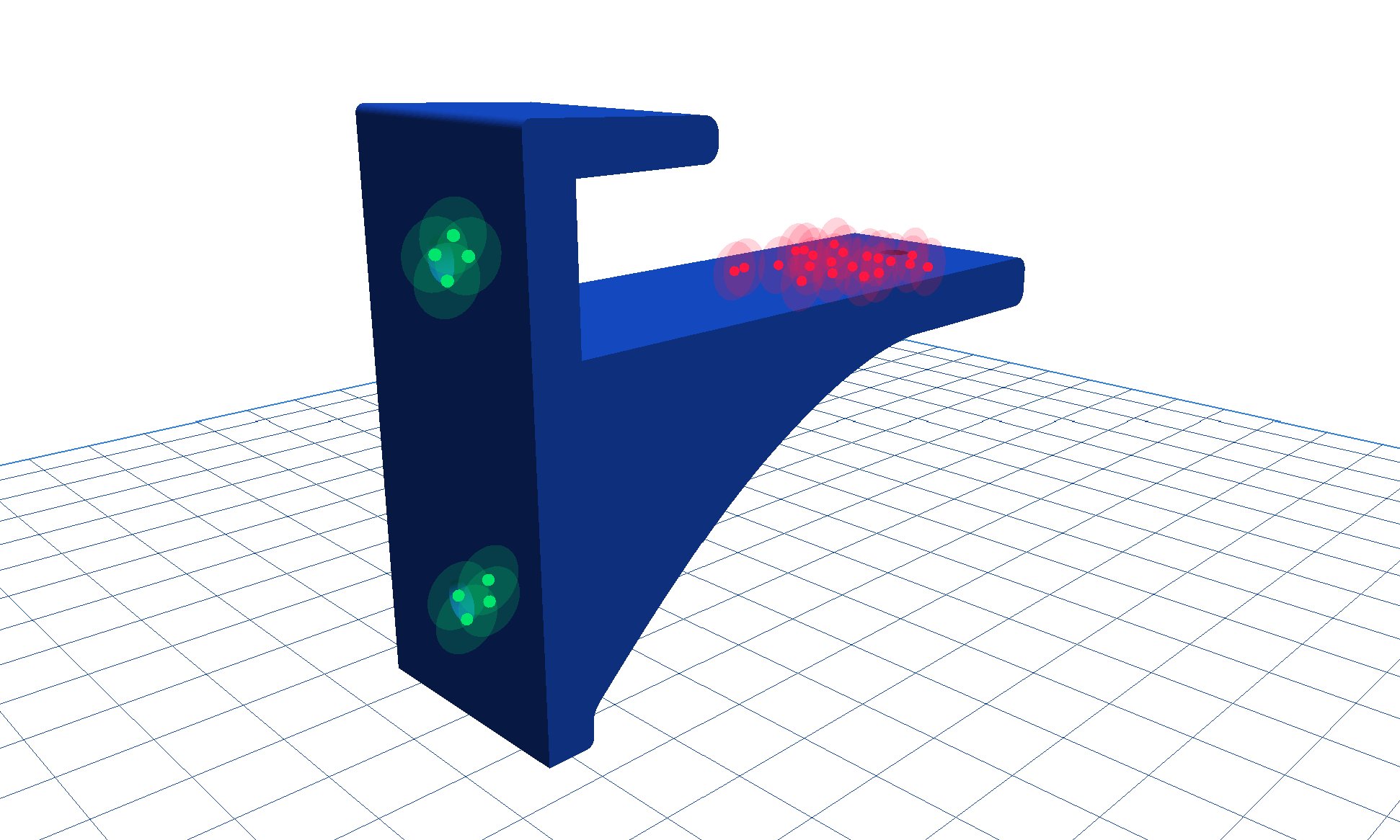
Any geometry, with or without holes. Formetric analyzes it and detects flat faces, cylindrical bores, and builds a volumetric representation automatically.
Click where the part is fixed. Click where the load goes. Magnitudes in real Newtons — no relative scales. Force vectors are configurable or normal to the surface.
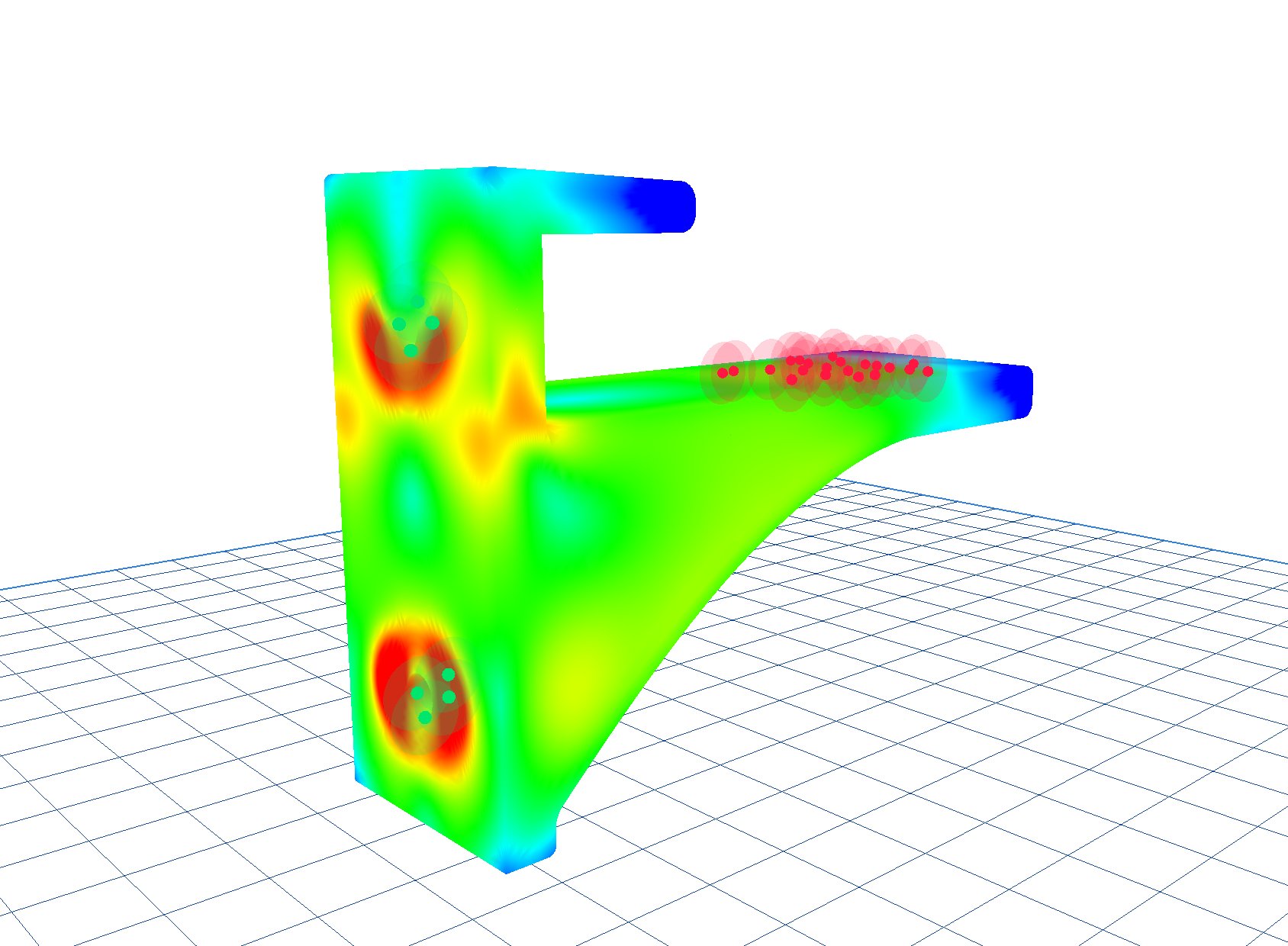
Volumetric finite element analysis computes the von Mises stress field across the entire part. Validated against beam theory. Safety factor reported automatically.
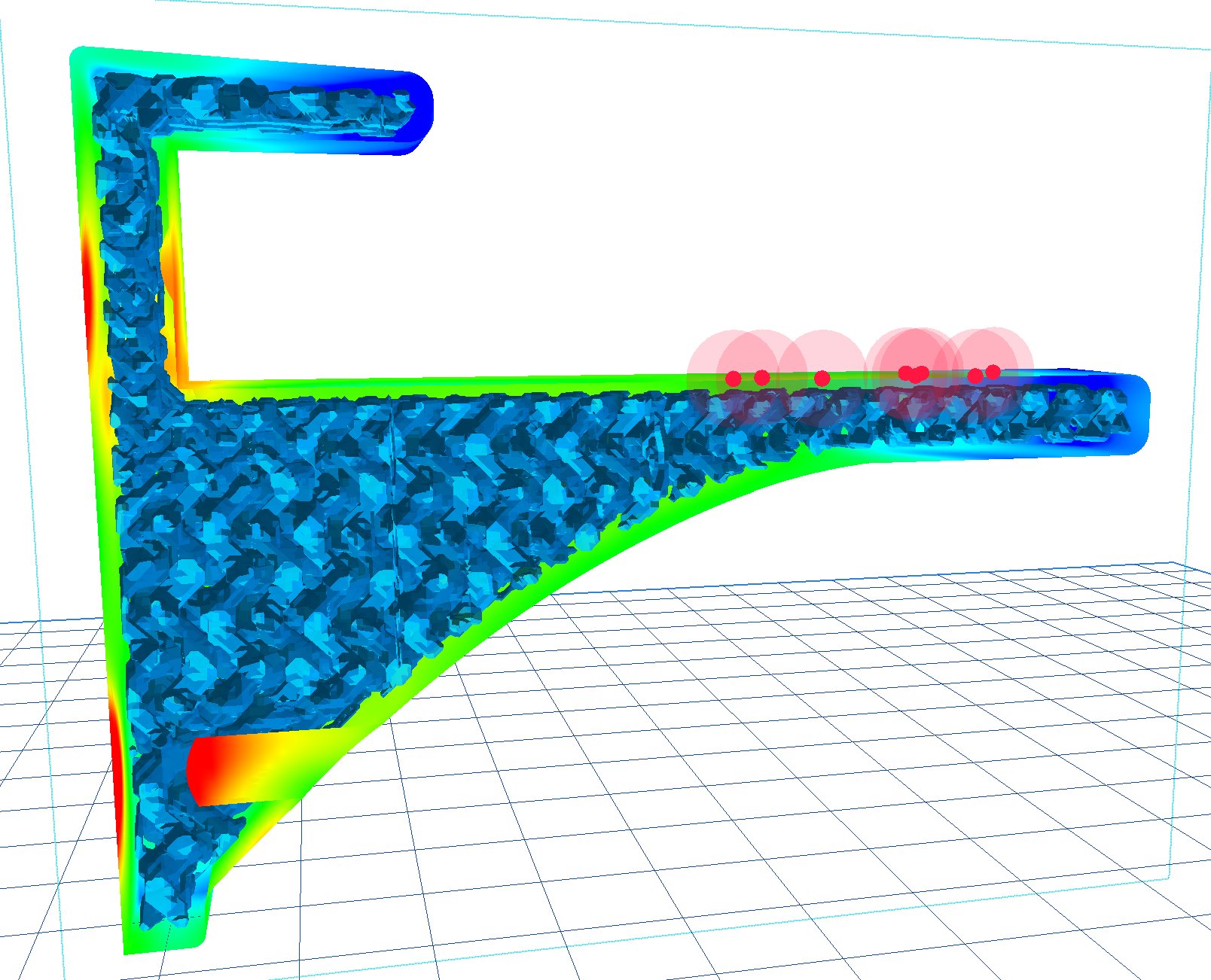
Formetric runs a second FEA pass on the infilled part — not just the solid. The safety factor against material yield, the volumetric stress distribution, and a validation ratio against analytical theory tell you exactly how the part will behave before you print a gram.
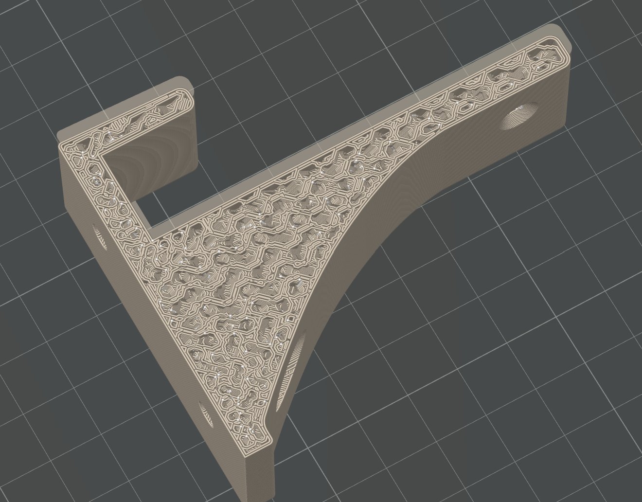
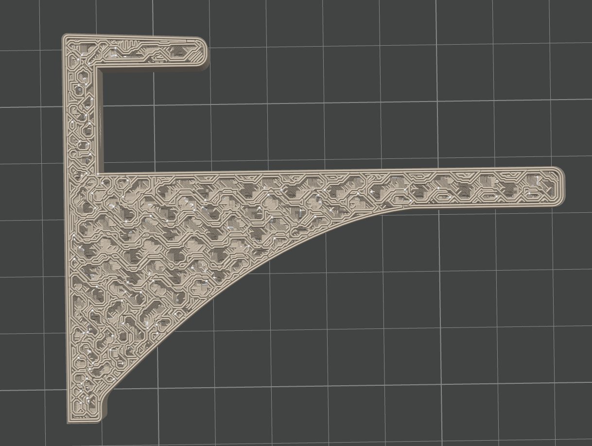
The Chirped TPMS routes small cells where stress is high and large cells where it isn't. No double walls, no artifacts. Output: a printable STL ready for Bambu Studio, PrusaSlicer, or Cura.
Every step you just saw runs inside the actual Formetric application. Below: real screenshots from the software, and from print-ready output loaded into Bambu Studio.
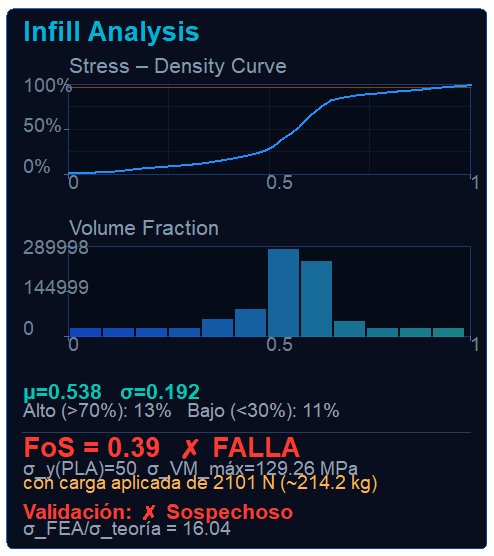
FoS = 0.39 ✗ FALLA, σVM_max far above PLA yield, and σFEA/σtheory = 16.04 ("Validación: Sospechoso"). This is the post-infill validation working: the part would have broken in the printer, you find out before pressing print.
Compared with the closest competitors at the same problem: structural FFF parts where weight and strength matter. Each tool excels at something — Formetric is the only one that covers the full FFF pipeline.
| Feature | Formetric | stecs3D | nTop | Novineer (NoviPath) |
Slicers (Bambu / Cura) |
|---|---|---|---|---|---|
| FFF/FDM-native workflow | ✓ | ✓ | ✗ general-purpose | ✗ Stratasys industrial | ✓ |
| FEA-driven adaptive infill | ✓ | partial | manual setup | analyzes only | ✗ |
| Continuous gradient (vs zones) | ✓ | 4 discrete zones | ✓ (manual) | ✗ | ✗ modifier meshes |
| Closed-loop post-infill validation | ✓ | ✗ solid-only FEA | multi-step manual | predicts, no redesign | ✗ |
| TPMS patterns supported | 7 verified | 2–3 | many (build yourself) | none | 1 (gyroid) |
| Direct STL in/out | ✓ | ✗ proprietary | ✗ proprietary implicit | ✗ G-code only | G-code only |
| Real Newtons (not abstract scales) | ✓ | ✗ relative | ✓ (manual) | ✓ | ✗ |
| Lab-validated (ISO 178 + ISO 527) | ✓ | — | — | — | — |
Triply periodic minimal surfaces (TPMS) are the mathematical sweet spot for FFF infill: smooth, isotropic, and self-supporting. Formetric supports the seven that matter — all experimentally validated.
TPMS surfaces are smooth and continuous. They print without internal supports — even at low cell density.
Equal mechanical response in every direction. No weak interlayer planes like rectilinear infill.
Minimal surfaces by definition route material with the lowest possible mass for a given mechanical response.
Cell size scales smoothly with stress, from tiny (high-load zones) to large (low-load zones). No banding.
Formetric is benchmarked against control configurations using normalized testing protocols. Three configurations are compared at equal mass:
5 replicates × 3 configurations × 2 tests = 30 specimens. 3-point flexural per ISO 178 and tensile per ISO 527-2 type 1BA, scaled to host the TPMS period. Statistical analysis with Welch's t-test.
Formetric is in private beta. Request access and we'll get you onboarded with one of the team.